At some point your project is going to go on its wheels. You can save yourself some work hours (and make the car feel pretty decent the first time you start it up) by pre-aligning the front suspension previous to putting weight on the tires. The bushing style control arms (A-arms to you hotrodders, wishbones to you Brits) of book-built Locosts are straightforward enough, plus there's not much you can do to adjust them. The only adjustments are camber (by moving the rod end on the upper control arm; thread in for more negative camber) and toe (thread the tie rods in for toe in, out for toe out).
All-ball control arms add some complexity, but the benefits are well worth the trouble. Replacing the bushings with ball rod ends can significantly reduce "compliance" -- the effect of suspension geometry changing under load, due to frame flex, control arm flex, and suspension bushing elasticity. Ball rod ends also allow straight load paths (indeed they pretty much demand straight load paths) from their attachment points on the wheel spindles to the suspension brackets on the frame. This reduces control arm flex, and allows lighter control arms for any given strength and rigidity.
And so, finding the advantages outweigh the disadvantages*, we've departed from The Book (that's Ron Champion's Build Your Own Sportscar for as Little as 250 £; the book that started this Locost thing) and changed to straight control arms and ball rod ends for the Whippet.

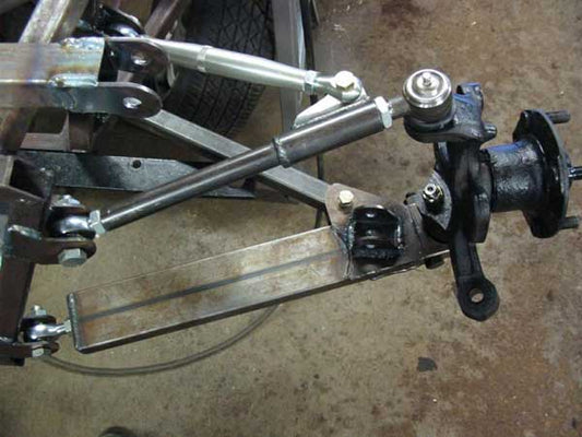
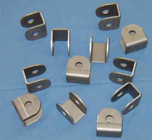
Here's an early CMC iteration of the Whippet-style upper control arm. It's for a narrow track Locost (using an early Toyota Corolla rear axle) and the tubes are 44 degrees from parallel. To avoid binding and to keep the loads on the ball joints as radial as practical (radial because ball rod ends are considerably weaker in axial loads than radial loads -- 85 to 90 percent weaker in most applications; practical because wide track cars have tube angles as tight as 28 degrees from parallel) the chassis pick-up points (suspension mount brackets on the frame) are canted toward each other. It is our understanding that all CMC Locosts shipped after May of 2004** had the Whippet style*** front suspension.
Before that, CMC made interim kits that had ball rod ends instead of bushings on otherwise "book" control arms, which fit "book" suspension brackets and bracket placement. I've set up one car that used that style suspension (the Grassroots Motorsports three-day-build Miata Seven) using the technique described below and it worked pretty decent, though I favor the Whippet (straight arm) style. For "book" suspension, skip steps as appropriate; this will still get you in the ballpark.
-
1) Put your chassis on four jackstands, on a flat floor. Shim the jackstands as needed to make the car parallel to the floor. The accuracy of your alignment will be directly proportional to the flatness of your floor and the levelness (is that a word?) of your car.
-
2) Thread a locknut onto each rod end; run the nut all the way to the ball end of the threads (finger tight). Use real lock nuts. Using conventional full nuts will cost you some adjustment range.
-
3) Using a felt pen, mark the threads of each 1/2" rod end at 3/4" from the threaded end, and the 5/8" rod ends at 1" from the threaded end****.
-
4) Thread the rod ends into the control arms, until the felt pen marks are just barely visible. Now turn them in a little more (if needed) so the balls will line up with the bolts in the frame suspension brackets (aka "chassis pick-up points").
-
5) Bolt the control arms in place on the frame. Don't bother putting nuts on the bolts; you'll be taking them out again several times.
-
6) Bolt the wheel spindles (with hubs but no wheels) to the control arms. The techniques vary depending on which donor car sourced your spindles. Finger tight is plenty for now. If your spindle-to-control-arm mounting system uses nylock nuts for the upper attachments, put the nylocks aside for now and use plain nuts (otherwise you'll wear out the nylocks during the adjustment process).
-
7) Mount the brake disks on the hubs. For some donors, the wheel holds the disks on; if so for yours, put a short length of plastic tubing (or use lots of washers) over each wheel studs so you can hold the disks in place with lug nuts.
-
8) Tie the lower shock mount to the upper shock mount with a piece of sturdy twine (or flimsy rope), so the lower control arms are parallel with the floor. (hey, it's easy to measure and it's close to where your ride height will be when you're ready to roll).
-
9) Using two straight edges, a tape measure, and some tape to hold the straight edges to the brake disks, set the wheels so they point straight ahead.
A leftover length of 1" square tube makes a good straight edge, but the very best straight edge is a beam of light. A laser level taped to each brake disk is very handy. Don't bother with the bubble, just make sure the base of the level is held flush against the disk.
-
10) Using a carpenters' square, adjust the rod ends as needed to put the brake disks perpendicular to the floor and parallel with each other. This can be done with measurement***** and math, but at this stage, trial fittings go fast and if you're within a turn of spot-on, you're good enough for now. Two important points:
--Turn the rod ends in (clockwise) only. If the spindle has camber (the top of the disk is outboard of the bottom of the disk) shorten the upper control arm (by turning its rod ends in); if the spindle has negative camber, shorten the lower control arm. If you adjust the rod ends out of the control arms, you'll have insufficient thread inside.
--Turn the 1/2" rod ends on each control arm as a pair; that is, if you turn the front rod end in 6 turns, do the rear rod end on the same control arm 6 turns too.
-
11) Put the suspension spacers in place on the rod-end-to-chassis-pickup-point bolts (the bolts installed in Step 5) and install shims (thin washers) as needed for symmetry******. With one each 0.20" and 0.10" long, 5/8"OD, 1/2"ID stainless steel spacers, and three thin (they call them 'light' in the av biz) AN washers, one can go from one side of the bracket to the other by relocating spacers and washers. The photo below shows the rod end centered in the bracket. Note that our quick adjust control arms don't need shimming; a pair of 0.20" spacers is all they need (see Works in Progress--Suspension).

-
12) Set the caster so it's the same on both sides of the car. Since driving is what's going to tell you if you want more or less caster, don't aim for any particular absolute in this preliminary set-up.
Looking at the side of the car, caster is the off-of-upright angle of the steering axis of the wheel. Your car needs positive caster, with the top pivot point rearward of the bottom pivot point (like the front forks on a motorcycle). More caster increases straight line stability (and thus, increases steering effort) and less camber has the opposite effect (less stability, lighter steering). How much caster you'll want is a matter of taste (it generally runs between 4 and 6 degrees), but it's a good bet your taste will run to similar steering effort and feedback for left and right turns, so set both sides the same.
You may find the caster angle easier to measure with the disk off the spindle (you're looking for the line between the two ball joints that pivot when the wheel is steered); I tape the disk to the spindle and eyeball a line on the disk; marked with masking tape or felt pen depending on which one's closest. I usually measure the angle with a prop pitch protractor from Warp Drive Inc (a carbon fiber aircraft propeller manufacturer), but a carpenter's angle finder did a good enough job on the Grassroots car, and simply whacking a matching angle (the floor to pivot line angle) out of a big piece of cardboard is perfectly acceptable, since you don't need to know what the angle actually is right now, just that it's the same for both wheels.
Find the caster angle of one wheel, and match the other to it by adjusting the 1/2" rod ends in one (or both) control arm(s) for the wheel you're adjusting. Moving the outboard end of the upper control arm back increases camber, as does moving the outboard end of the lower control arm forward; reversing those directions decreases camber.
To move the outboard end of a control arm back, thread the forward 1/2" rod end out and the rear 1/2" rod end in; the same number of turns for both.
Which control arm should you adjust? The one you shortened the most during Step 9. That way you're least likely to overextend a rod end -- which will show itself because the felt pen mark (Step 3) will be exposed. If that happens, you'll need to go back in until the mark disappears (and out the same number of turns on the other rod end you're adjusting) and finish the job by adjusting the other control arm the opposite way.
-
13) Are any of the marks made in Step 3 exposed? No big deal; just thread the marked rod end in (and count turns) until the mark is just on the edge of the control arm (or disappears completely, if you prefer). Now thread in the other three 1/2" rod ends on the control arms for that side of the car, the same number of turns. This shortens both control arms equally, and gives adequate thread contact for all the 1/2" rod ends on that side. This maneuver won't change camber or caster, though it will bring the wheel slightly closer to the car, narrowing the track insignificantly (about 1/4" for six turns), and you'll have to redo the shimming of Step 11..
-
14) Repeat Step 10, using only the 1/2" rod ends, and moving them in pairs (as you did in Step 10) so you don't change the caster. Get as close to perfect as you can, which won't take long because:
--Step 10 should have put you darn close already, and Step 12 won't have changed things much.
--Once you're within 1/4 turn of a ball joint from where you want it, you're as close as you can get. If a half turn (the smallest adjustment you can make) one way puts the disk out from vertical, and a half turn the other way puts the disk in from vertical, pick the one that looks closest and call it good.
-
15) You can break out your trigonometry textbook from yesteryear, or trust me on this: three full turns in with a 5/8" diameter 18-thread-per-inch rod end will put you very close to 1 degree of negative camber, which is a good place to start. So, once you're happy with Step 14, screw the upper control arm outboard rod ends (the ones that attach to the spindle) in as desired for your chosen negative camber.
If your suspension is more flexible than ours (you have curved control arms instead of straight, or rubber bushings instead of metal ball rod ends) give yourself another half turn or so. If you're running racing tires and are convinced you should start off at 1-1/2 degrees of negative camber, then turn the rod ends in 4-1/2 revolutions. But if it's a street car, try it at one degree (three turns) and see how you like it before you go wild and crazy.
-
16) Look for exposed felt pen marks on the rod end threads; if so, deal with them as per Step 13. Double check the shimming (Step 11) to avoid side load on the rod ends in the chassis pick-up brackets. Snug down the lock nuts on all the rod ends, install and tighten the locknuts on the chassis pick-up point bolts, tighten the control arm attachments to the spindles (Nylocks? Cotter keys? Now's the time to use them), replace the twine of Step 8 with coilover shock absorbers, and you're dang near ready to roll.
Thus end the oddball aspects of the Whippet front suspension. All you have left to set is toe, which is adjusted the same as any other car. Toe in (the fronts of the wheels closer together than the rears of the wheels) makes a car more stable in a straight line, toe out (the fronts of the wheels farther apart than the rears of the wheels) makes a car quicker to go into turns. Too much of either one is a Bad Thing; too much toe out and you're driving a train, too much toe in and it'll go into turns all by itself.
Cars are rarely run with no toe at all, but that's my recommendation for initial setup; loosen the locknuts on the tierod ends, install the tierods in the steering arms of the spindles, use the straight edges (or laser levels) and thread the tierods in or out as needed to make the brake disks parallel to each other in toe. You can set your toe before you take the chassis off the jackstands (if so, do it before you replace the twine with the shocks; sort of a Step 15-1/2) or after the car is on the ground.
Mark the tierods so you can get back to the no-toe position without remeasuring, and after you've driven enough to get used to how it handles with zero toe, try some small adjustments both ways. And speaking of adjustments, if/when you readjust either caster or camber, you'll have to readjust toe and your tierod marks will have to be redrawn.
Jack McCornack
*The only real downside (IMHO) to straight tube control arms on Locosts and the like is that with curved upper control arms, one can squeeze in larger diameter coil-over shock absorbers. There's a fake downside too; the fact that curved tunes are weaker than straight tubes means that, in a mishap on street or track (a curb strike, for example), one is more likely to bend a control arm and less likely to bend a frame tube. That's the theory. I ain't buyin' it.
**We're not complaining, mind you. Kinetic was a CMC dealer back then, at least on paper, and it was an improvement I insisted on (and built the tooling for). We swapped some (non-exclusive) suspension design rights for some (equally non-exclusive) fiberglass design rights, and everybody was happy.
***Well, we need to call it something, right? It's not how Colin Chapman was building Lotus Sevens fifty years ago, or how Ron Champion built the Locost fifteen years ago, or how CMC built Locost kits before we brought them our Whippet fixtures, so we'll pat ourselves on the back for coming up with radial load control arms for Locosts.
****An aviation rule of thumb is a rod end should be inserted at least 1-1/2 times its diameter; that's 3/4" for the 1/2" rod ends and 15/16" for the 5/8" rod ends. I round the 15/16" up to an inch because the outboard rod end gets a bit of beam loading under heavy braking, and shorter = stronger and stiffer.
*****Each turn of the 1/2" rod ends moves the control arm roughly .045"; the 5/8" rod ends bring the end closer to the frame by roughly .050" per turn.
****** Asymmetrical placement will cause camber changes as the suspension travels, which is possibly a good thing (though if so, it's way beyond m