Opinions presented here do not necessarily reflect the opinions of Kinetic Vehicle's management and…wait a minute; sure they do, I'm KV's president and I can write whatever I want. Bwaa ha haaa…
We will add an Op-Ed page for opposing opinions, should anyone care to write one up, and since most folks mount suspension rod ends at right angles to the chassis centerline, surely opposing opinions are out there.
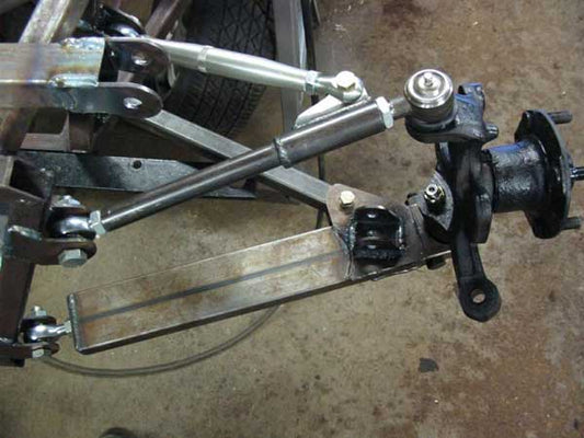
About three years ago we introduced a change to the venerable Locost front suspension: we cut the chassis tubes that carry the front suspension (LA and LB at the front of the car, and FU1 and FU2 right behind) at compound angles so the front suspension brackets faced the load they carried. Our objectives were to reduce the axial loads on the rod ends and reduce the bending loads on the control arm tubes (and on joints in the tubes, if any). Others had used rod ends in place of The Book's bushings—in the case of CMC, quite literally in place of bushings; there was no change in the bracket size or bracket placement—which had the benefit of making the suspension more adjustable. It also made bracket placement less critical, since (and this is the beauty of ball rod ends) rod ends can function when misaligned (at spectacular angles, no less; 20 degrees is typical) without binding, and bushing's bracket pairs have to be set directly in line with each other, or the bushings will bind and/or wear.
The problems with that approach are:
—To get the rod ends to meet the brackets at close to the angle of the bracket, either the control arm tubes have to be bent, or threaded slugs have to be welded, at an angle, to the ends of the tubes. Because of the bend/kink in the tube, compression or tension loads are translated into bending loads, and as anyone who has played with soda straws can tell you, bent or kinked tubes are far weaker in compression than are straight tubes.
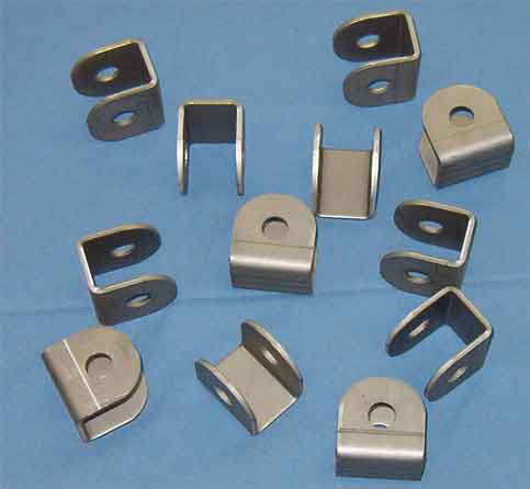
—Bushing-width brackets with 1/2" rod ends have about an inch of play, which puts an unnecessarily large beam load on the mounting bolt,
—The rod ends themselves see an unnecessarily large axial load (that's the load in the direction that's trying to force the ball out of the socket) which…well, large axial loads try to force the ball out of the socket and rod end ball joints aren't designed to take much of that.
On most spec sheets, rod ends are rated at their radial load capacity, and axial load capacity is typically 10% to 15% of radial load. As a general rule, cheap two-part rod ends (a body and a ball, with the body swaged around the ball) have the highest ratio of axial load to radial load (15%) and that ratio drops as the quality and strength of the rod end goes up. If you're using a medium- to high-strength rod end, don't expect an axial load rating greater than 10% of radial rating, and the radial load rating is usually the only rating you can get without working for it. In other words, if a 1/2" rod end is "rated" at 6500 pounds ultimate, it's probably good for 650 pounds ultimate axial load.
In loads that are a blend of axial and radial loads, the weak side is the determinant side. The 45 degree load capacity is not an average of the axial and radial capacity, it's the axial capacity that's the weak link, and at 45 degrees that typical/hypothetical 6500 pound rated rod end is good for less than 1000 pounds (900, 920…somewhere in there).
So…keep your rod end axial loads low, your tubes straight, your brackets skinny, and avoid unnecessary welds, and your control arms will be stronger stiffer and lighter than if you don't.
Jack McCornack